
RF performance testing
Vector network analysis and RF verification for return loss, insertion loss, isolation and repeatable interconnect performance.
Engineering support for RF performance testing, cable phase matching, 3D CAD data, custom cable assemblies and millimeter-wave interconnect optimization.
Contact engineeringVector network analysis and RF verification for return loss, insertion loss, isolation and repeatable interconnect performance.

Phase matching and calibration for RF cable sets, balancing electrical length, amplitude consistency and VSWR performance.

Project-ready custom 3D CAD models and drawings for design review, including DWG, DXF, STL and IGES delivery formats.

Custom RF cable solutions by interface, cable type, length, strain relief and operating environment, from samples through production.
Millimeter-wave RF coaxial interconnects are critical signal-path components for communications, radar, navigation and advanced RF test systems.
At short wavelengths, connector geometry, materials and assembly precision directly affect attenuation, reflections and coupling. KLT engineers impedance matching, loss control and mechanical stability as one system.
Optimized 2.92 mm millimeter-wave cable assemblies are verified across DC–40 GHz with VSWR targets up to 1.25.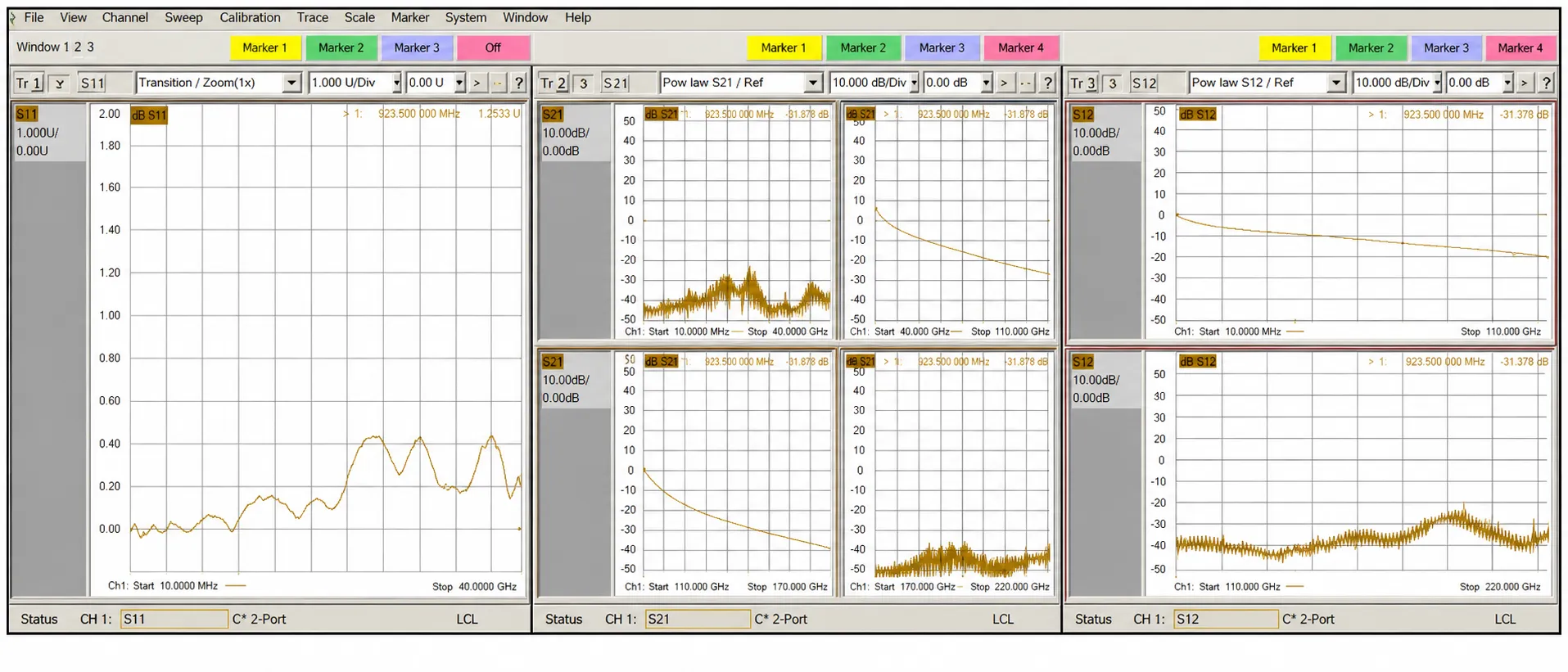
From high-frequency connectors and microwave cable to system-level test support, KLT builds complete signal paths for demanding programs.
Precision RF interconnects combine microwave and millimeter-wave cable assemblies, RF connectors and board-level structures for radar, satellite communications, test and advanced manufacturing.
Connector and cable designs are engineered together for impedance continuity, low loss and repeatable mechanical performance.
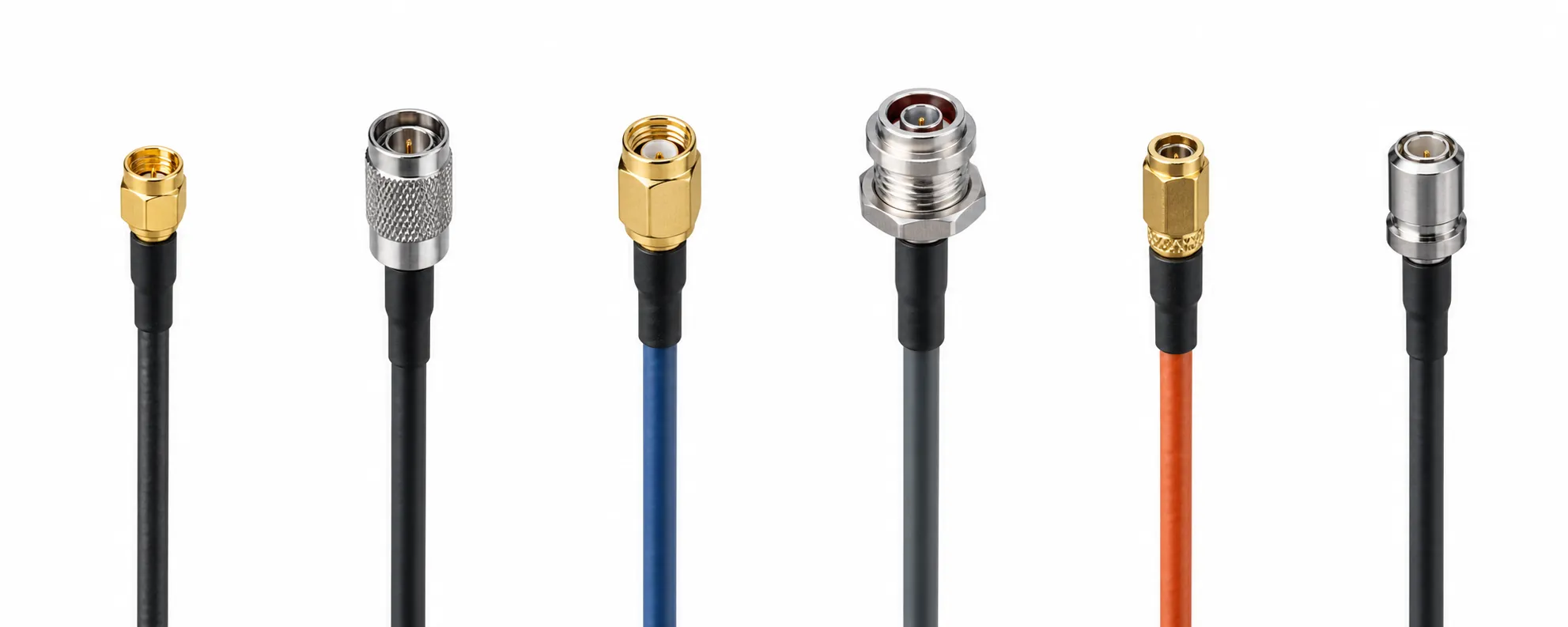
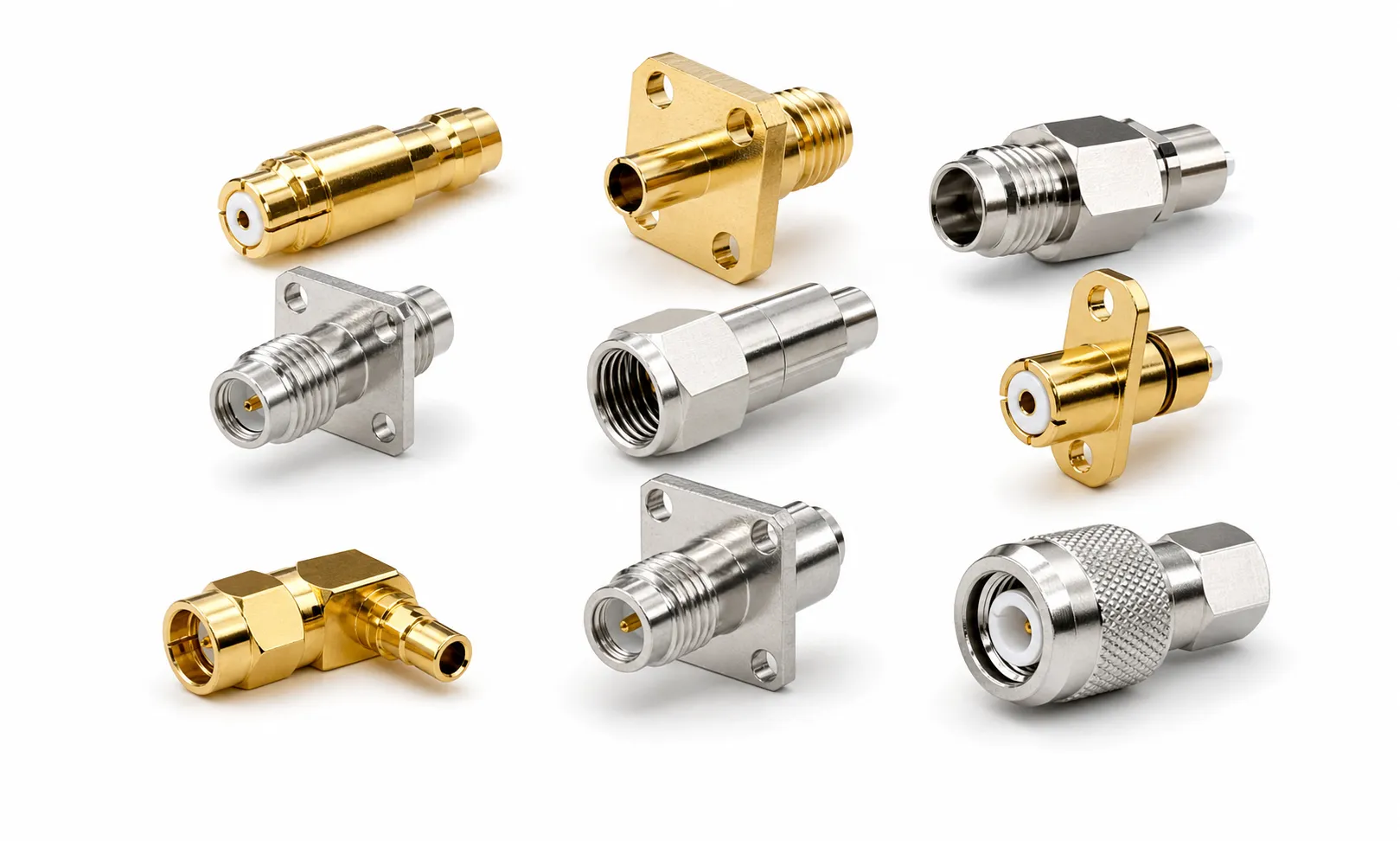
Choose RF interfaces, mechanical formats and termination options that suit the application while maintaining assembly efficiency and lead-time control.
ANY RF CONNECTOR · ANY MICROWAVE CABLE · ANY APPLICATION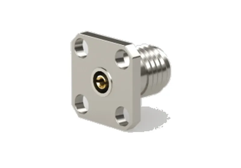
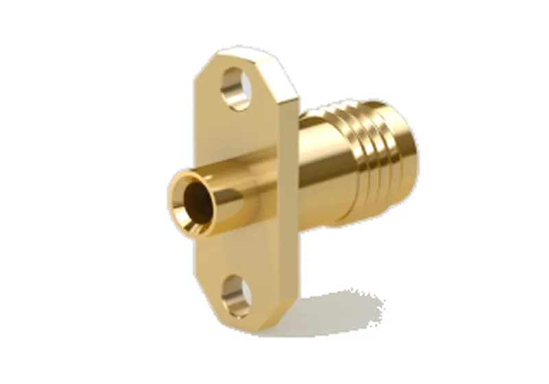
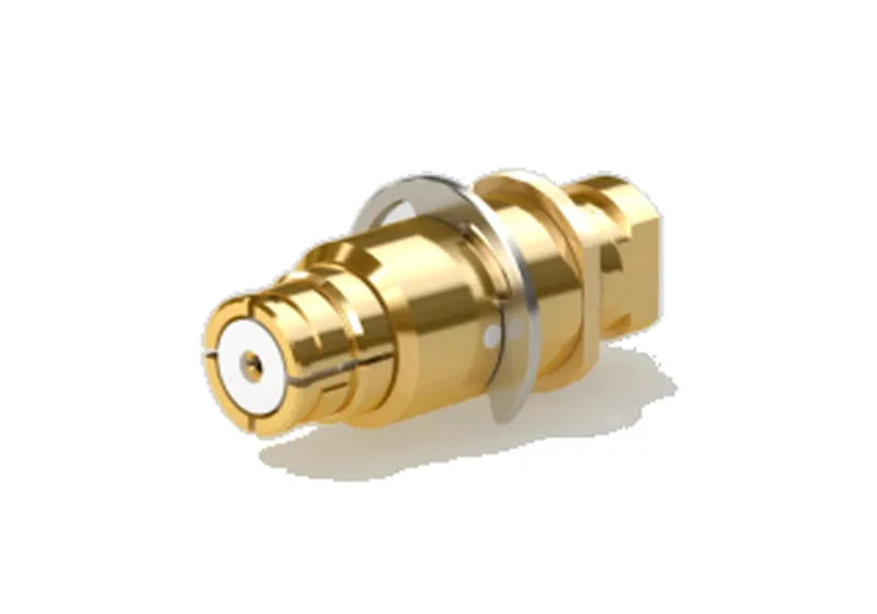
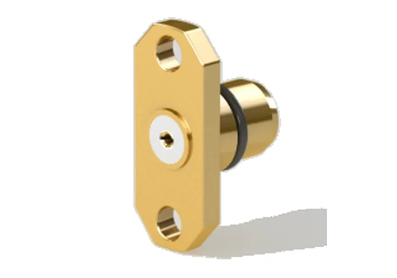
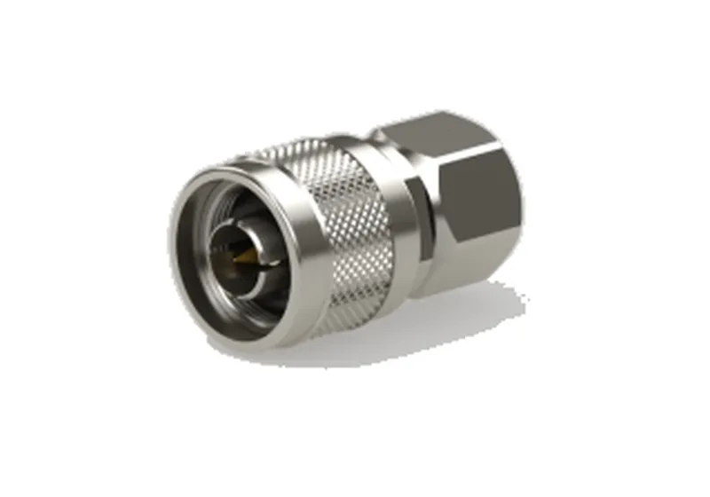

Five project-proven interconnect structures for high-frequency, high-density, multi-channel systems with varying board spacing requirements.
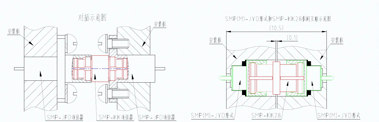
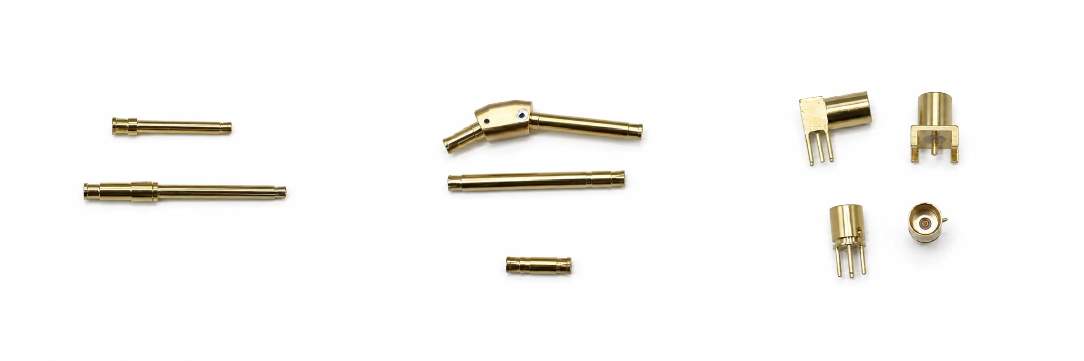
Use SMP, SSMP and WMP series products for board-to-board interconnect — high installation density, excellent vibration resistance and high operating frequency. Mount receptacles on both module panels; connect via a female-to-female adaptor in the middle.
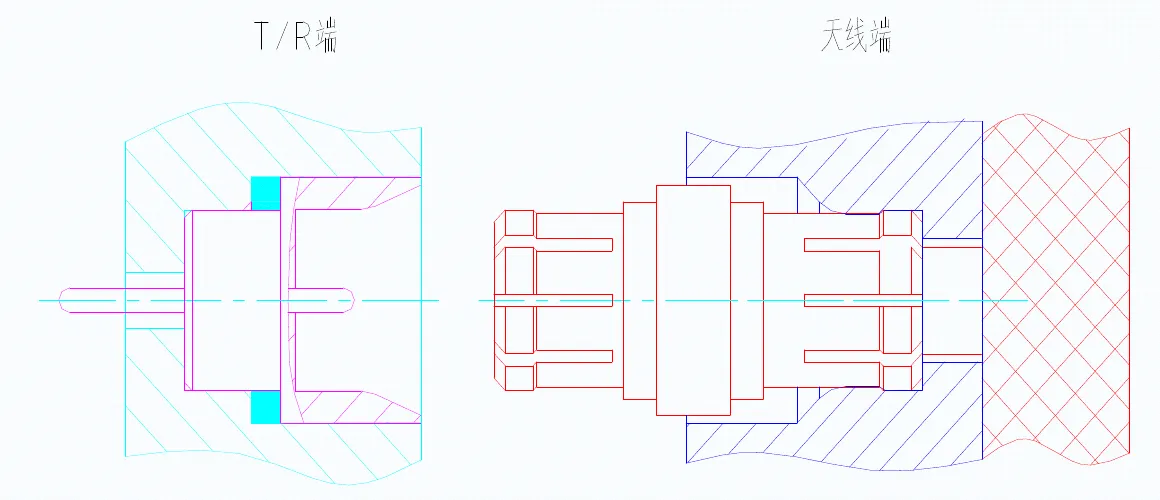
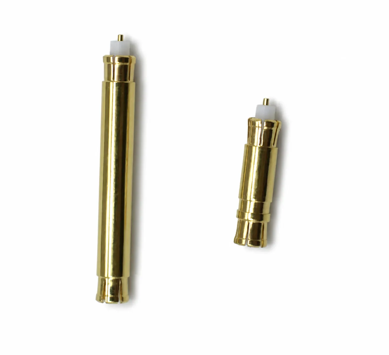
For integrated antenna structures with up to 3 000 channels and spacing as small as 3.5 mm × 3.5 mm: the T/R side uses standard receptacles with a female-to-female adaptor; the antenna side integrates the SSMP‑J interface directly into the structure panel; the inner conductor contacts the antenna π‑point via spring pins.
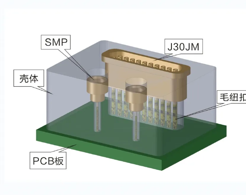
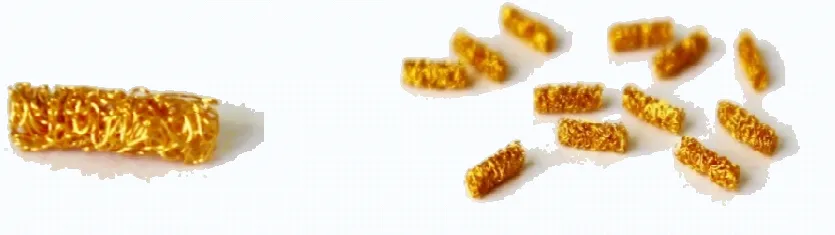
Fuzz buttons are formed from gold-plated wire wound through a specialised process. They can compress axially by 10%–30% of their length; after compression, end-face spring force makes reliable electrical contact. They carry either high-frequency or low-frequency signals and can integrate multiple signal channels on a single board.
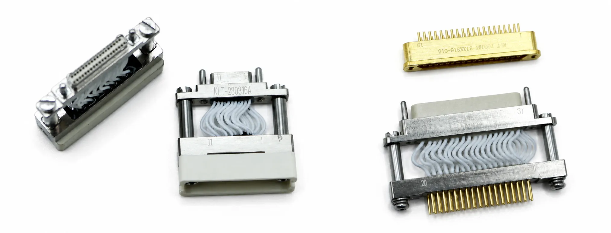
When boards require rigid hard-mate interconnection, floating plugs reduce mating difficulty and prevent connector damage from rigid alignment. Also accommodates larger board spacing, enabling plug-to-receptacle mating without an additional adaptor.
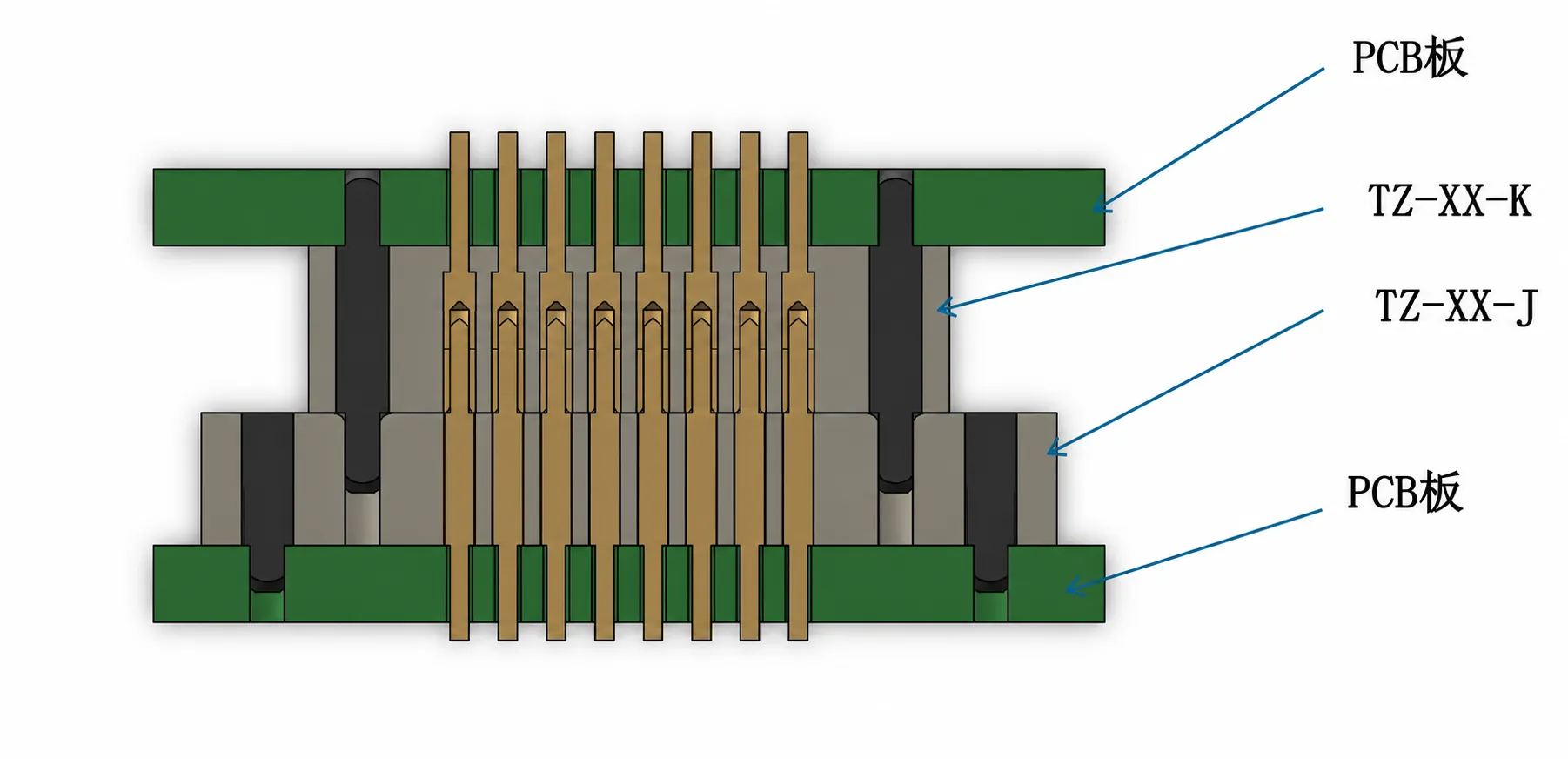
The TZ series uses rigid pins mated with slotted receptacles for multi-contact board-to-board signal transfer. Contact spacing is 1.27 mm × 1.27 mm; stack height is customisable to user requirements. Mating force is low and installation is straightforward. Because the contacts are rigid, simultaneous mating of multiple connectors is not recommended.
For standard selection, alternates, rapid prototypes or harsh-environment designs, tell us the interface, frequency, space, environment and quantity.